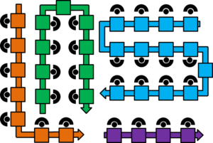
 The layout of a line can make quite a difference in the performance of your line. The U-line is most famous, although in my view while good it may not be the right thing for all situations. There is also the I-line, the S-line, and the U-line. In my last post I described some general thoughts on line design and took a look at the big picture. In this post I want to look at and compare actual line layouts, in particularly the I, U, S, and L layout. Let me give you an overview of the different options.
I-Line
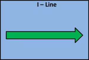 The simplest line is the I-line, a straight line. This is common for very short lines or for automated lines. It is also used for processes that cannot have bends in the line for technical reasons (e.g., the float glass process for producing flat glass, where the 100-meter-long piece of glass naturally can’t go around corners until you cut it into smaller pieces, or rolling mills or paper plants where the sheet metal or paper strips also cannot go around corners very easily).
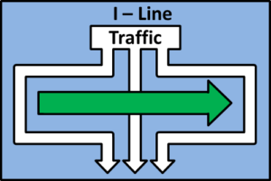 The advantage is easy access from both sides for both material and operators. On the other hand, if this type of line is too long, it may reach the limits of the building you have. Additionally, a long I-Line may act as a barrier, and both material and operators always have to go around the line unless you incorporate a sort of bridge or other crossing.
Finally, due to the length of the line, managing and supervising the line involves more waste for the supervisor and possibly also the operators due to walking distances. An operator may be able to tend to his own process and maybe the two adjacent processes, but everything beyond that may involve too much walking.
U-Line
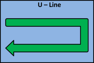 The U-line is actually quite famous in lean manufacturing. Often it is praised as the best possible line layout. This U-shaped line is indeed quite nifty, but it is not a universal solution for anything.
The U-line is used mostly for manual manufacturing lines. A U-line is less ideal for fully or mostly automated lines. The main benefit exists if multiple operators are within the “U” of the line. All the operators are within the “U,” while the material is supplied from outside of the “U.” This of course requires devices and tools to bring the material across the line from the outside to the inside. Slides and chutes are often used to bring material over the line, and roller conveyors for material from underneath of the line. Often, a separate operator (usually called a “point-of-use provider”) is in charge of refilling these devices from the outside using material provided by logistics. Overall, refilling material in an U-line is not as easy as with an I-line, but often other benefits make this effort worthwhile.
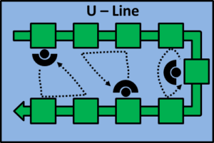 The advantage of the U-line is the ability of workers to tend multiple processes within the line. Since not only the adjacent workstations but also the workstation “on the other side” are close by, the worker can manage multiple work stations. Therefore this type of line is well suited for multi-machine handling.
An additional benefit is that a worker can tend to both the beginning and the end of a line. If the line has a breakdown or problem, the worker can tend to the section in trouble and can temporarily neglect the other end of the line. Overall, breakdowns and other problems may be fixed faster than in other lines.
This is, for example, popular with Chaku-chaku lines. Chaku-chaku (ちゃくちゃくライン, 着々ライン) is Japanese for “arriving,” but also represents the sound of the process. In this line, the operator loads the machines and starts the process before moving to the next machine(s). The machine works independently and ejects the part afterward before the worker loops back to the machine. Automating ejection from a machine is much easier than placing a part in a machine, hence this Chaku-chaku line is often a good compromise between automation and manual labor.
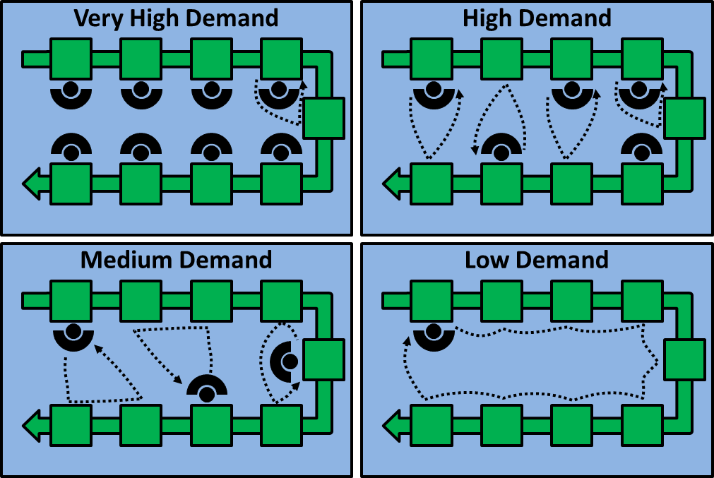
Since an operator can tend to multiple machines without excessive walking distances, this type of line is well suited to be scaled up and down by adding or removing workers. If demand is very high, you put a worker at every workstation and the total output goes up. If demand is lower, you reduce more and more workers from the line, until at the end only a single worker handles all the processes, producing only a few parts. Of course you would have to ensure that the machines are fast enough, and that the workers in the different settings all have similar workloads to avoid waiting times of operators.
S-Line
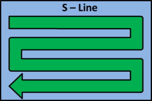 The S-line is often used for particularly long lines, as for example automotive assembly lines. These lines can easily be thousands of meters long. Putting them in a straight line would not only require a very long building but would also put quite a strain on intra-logistics material transport.
An S-shaped line can fit much easier in a manufacturing plant, and the logistics are also much easier to handle. Of course, you would need to create crossings and access points where forklifts and milk runs can drive in and out of the line without having to go all the way around. Since the spaces between the loops of the line need to be wide enough for forklifts and milk runs, operators usually tend only to the stations on their side and do not cross to the other side, although this may also be possible for lines requiring less material to be delivered from the sides.
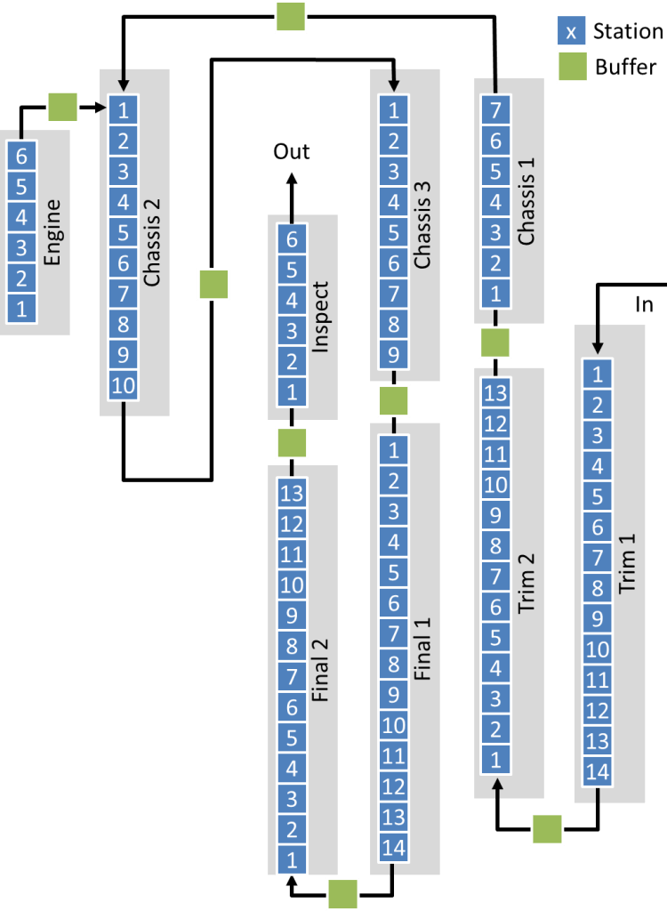
Often, these lines are created using multiple I-line segments arranged in an overall S-shape, with buffers at the turns of the material flow. The image shows, for example, the line layout of the Toyota Motomachi plant, where multiple I-segments are arranged in different loops, plus an engine production line merging with the main line during chassis assembly. The otherwise perfect S shape is broken by the Chassis 2 assembly on the left side, which was probably necessary to merge the engine assembly line with the main line. This may have been more difficult in the middle of the “S,” hence the Chassis 2 line was moved to the side of the system. For more on the Motomachi assembly line and how it changed over time, check my post Evolution of Toyota Assembly Line Layout – A Visit to the Motomachi Plant.
L-Line
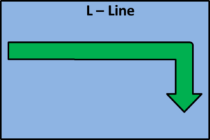 The L-line is usually not part of a grand design. Most L-lines are forced to be L-shaped by the available space in the plant (or by sloppy line design). They may also be useful if the inbound and outbound warehouse are at an right angle to each other. In the image shown, imagine the inbound warehouse to the left, and the outbound warehouse at the bottom, and the L suddenly makes sense.
They have similar advantages and disadvantages to the I-line, except they have an additional corner to go around. They are hence not that common.
Conclusions
And there you have it. These are the most common line layouts for normal flow lines. These will serve you for most purposes. Of course there are always more possibilities. For example, once I had to design the line layout of a distribution center, where packages are added to a circular line at one spot, and they go around the circle until they are picked off for a particular destination.
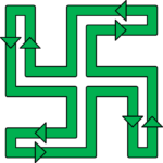
I spent quite some time on that design, and got a good solution. Ease of access, lots of space for the operators, efficient use of floor space, quite nice actually. I was just about to present this line layout proposal to management when I took a last look at it and … it turned out to be a swastika shape! With me being German – and working in a city that was destroyed and then occupied by the Nazis during World War II. That’s when I decided that maybe I should NOT leave a 30-meter swastika behind on the shop floor as the result of my work.
The Nazis ruined an otherwise perfectly good line layout option. The point I am getting to is that there are always more possibilities besides the I, U, S, or L. You have to do what is best for your situation. You could also use a cell, or maybe even use a job shop (although flow shops are usually better). In my next post I will present a few options for merging of production lines. Now go out, don’t build 30-meter big swastikas, and organize your industry!

Dear Chris,
thnaks for your great post regarding layout am optimizing layout as well so what is the decision matrix which can help us select the proper layout ,and another is question about Toyota Motomachi plant how they decide SWIP and operator work range
we are looking forward your another wonderful post:-)
all the best
I haven’t used decision matrices for line layout. I think they may be not ideal for line layouts. As for Motomachi : I don’t know, but I would guess from a mix of experience and some simple calculations. Especially for the buffer sizes: while there is some math available, it is usually better to do it by experience.
Thanks Chris got it and I think it is very important part of 3P process
I am Looking forward to seeing other wonderful posts:-)
EXCELLENT POST!!! CONGRATS…
Many thanks Frank & Sérgio for the compliments 🙂
Excellent article! Thanks a lot!
Good thought on last line layout. You need to step back and take final look for unforeseen issues before implementation. Good job in taking that step back!
The layout of the warehouse has a significant influence on the productivity of the warehouse. So, it is really essential to choose the best layout for the warehouse to enhance the efficiency and workflow of the warehouse. Better utilization of the space available in the warehouse is the key to get better profit. However, an adequate amount of space should also be available for the movement of different types of equipment in the warehouse to prevent any kinds of collision.
I am the owner of a small manufacturing facility. My operations leader is convinced that whole task design is better than assembly line or semi-automation. There are 5 to 10 material parts and or steps in the assembly of our finished good items. They can be automated or semi-automated with a 6 month ROI. Any thoughts on the right path? Is there a case for whole task design?
Hi Tom,
The question is how much work is the assembly from 5 parts/how long does it take? Generally, a worker should have work content between 30 seconds and 2.5 minutes (too short = boring; too long = learning curve, mistakes, hard to optimize/standardize). If the assembly happens quickly, it may be better to have one person work cells. If it is more than 2isch minutes, you may consider assembly lines.
The best approach in my opinion would be an experiment. Can you set up one production line to try it out? Have the line run for a month or so and compare performance, quality. Do it together with the people, because if your guys are against it from the start the workers can easily manipulate the outcome to make it fail.
Hope this helps,
Chris
Thanks Chris for tackling this subject, which is rarely discussed in scientific literature. I would like to know if there are any academic writing on this subject.
Hi Zou, not directly. But if you want a more formal citation of an official book, check out my “Collected Blog Posts of AllAboutLean.com“, which are available for free download.
Thanks Chris, very good article
Hi,
Is there any ideal human area space for this production line design?
Hi Susan, if it includes humans, an U-line is often preferred for shorter lines.